NP × NParks Control Panel · Operations Manual
A complete walkthrough of the desktop control panel for the NParks Weed Harvesting Boat: installation, first login, every page, hardware setup, and troubleshooting.
Contents
00 — Overview
The Control Panel is the onboard interface for operating and monitoring an NParks weed-harvesting boat: GPS position and routing, live battery telemetry over RS485, and (in progress) a camera feed, all from one full-screen kiosk application.
It is an Electron desktop app with five pages reached from the left sidebar: Home, GPS & Routing, Camera, Battery, and Settings, backed by a Node.js main process that talks directly to the battery hardware over a serial RS485 connection, and to two small Python services for weather logging.
This manual covers the app as currently built. The Camera page's live feed is not yet wired up; see section 10 for status and section 04 for what each page does today.
01 — Before You Start
Everything below is required to build and run the app from source. Items marked optional are only needed for specific features.
| Requirement | Used for | Notes |
|---|---|---|
| Windows 10/11 | Target platform | win32 |
| Git | Cloning the repository | |
| Node.js + npm | Running and building the app | Electron 41 toolchain |
| Python 3 | Weather logging services | Optional — Home dashboard weather tiles only |
| RS485-to-USB adapter | Battery (BMS) page | Optional until you connect real hardware |
| Java 17+ | Generating offline map data | Optional — only for building an .mbtiles package |
Two physical items are specific to this project and worth having in hand before you start: the battery pack assembly and the RS485-to-USB adapter that bridges it to the laptop running the app.
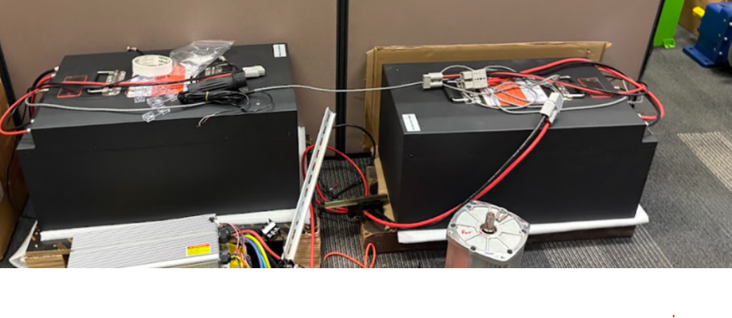
Battery packs — the two LiFePO4 packs (Battery 1 & Battery 2) with their BMS wiring harness and balance-lead connectors.
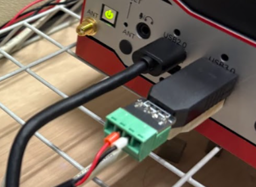
RS485-to-USB adapter — plugs into a free USB port; the green screw-terminal block is where the battery's A/B communication lines connect.
02 — Installation
This is the exact sequence; each step depends on the one before it.
Pick a working folder and pull the source down.
cmd
git clone https://github.com/Xovai/NP-X-NParks-control-panel.git
cd NP-X-NParks-control-panel
The project has two package.json files: the repo root and App/. Install both.
cmd
npm install && cd App && npm install && cd ..
serialport (the Battery page's RS485 connection) is a native module. If the app throws a module version-mismatch error on launch, rebuild it against Electron's Node version: cd App && npx electron-builder install-app-deps
The app can only be closed by entering an admin password; it's read from an environment file that isn't checked into git, so you set it once per machine.
cmd
cd App
copy .env.example .env
# then open .env and set:
ADMIN_PASSWORD=your-chosen-password
Skip this and the app still launches, but the exit dialog will reject every password; you'll see a console warning on startup as a reminder. There's no other way out of the kiosk window.
The launcher starts the background weather/camera services, then the Electron app itself. If you'd rather not use the terminal, open the App folder in File Explorer and double-click start-app directly:
cmd
start-app.bat
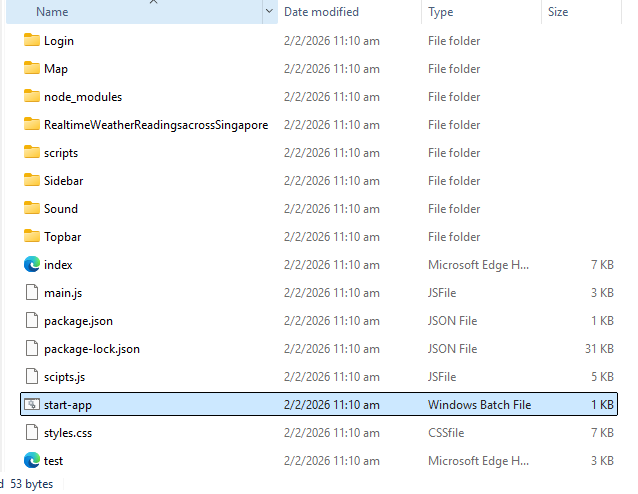
App/ folder — start-app is the Windows Batch File; double-click it to launch.
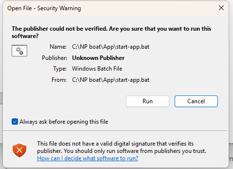
Windows will show an unknown publisher warning the first time; this is expected for an unsigned internal tool. Click Run to continue.
03 — First Run & Login
The app opens full-screen on the login page. Enter the standard operator credentials:
| Field | Value |
|---|---|
| Username | admin |
| Password | admin |
This is separate from the admin exit password configured in App/.env; login gets you into the app, and the exit password is only asked when closing it. On success you land on the Home dashboard.
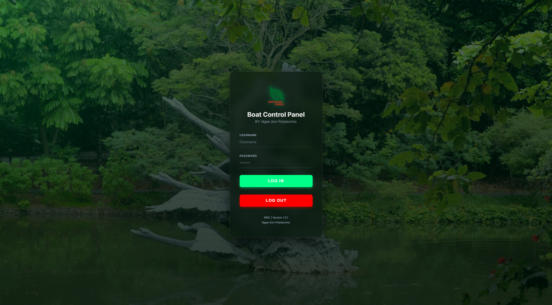
The login screen, as it appears full-screen on launch.
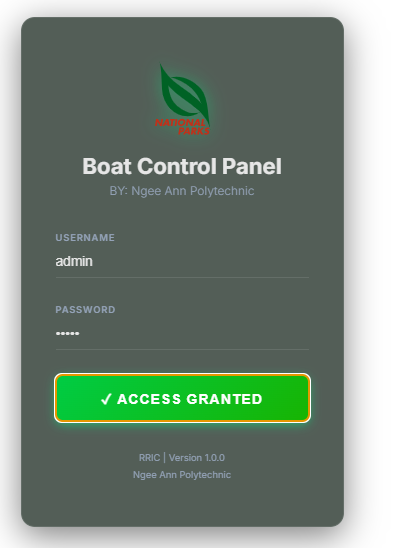
After correct credentials, the button switches to Access Granted and redirects to Home.
04 — The Five Pages
Navigate between pages from the left sidebar at any time; it also has a collapse toggle for a wider working view.
Dashboard
At-a-glance GPS map, current location, orientation (roll/yaw/pitch), and battery status; the default landing page.
Navigation
Full-screen map, live position, and the waypoint manager. Covered in detail in section 05.
In progress
Reserved for a live onboard camera feed. Not yet connected; see section 10.
Hardware
Live BMS telemetry over a direct RS485 connection. Covered in detail in section 06.
Configuration
Serial port, camera IP, and map preferences. Covered in detail in section 07.
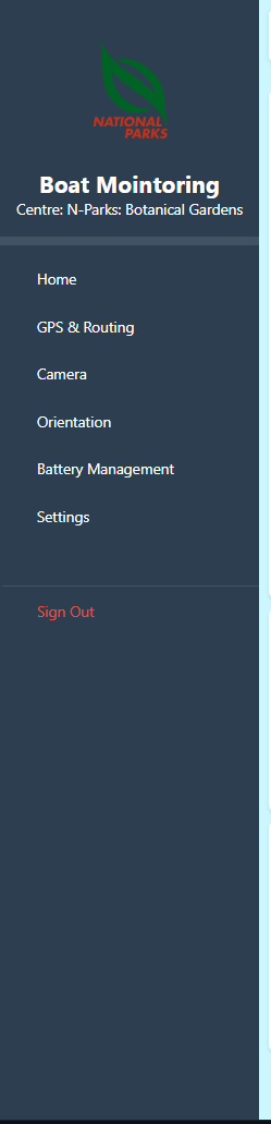
The sidebar is a shared component loaded into every page, so the navigation stays identical everywhere.
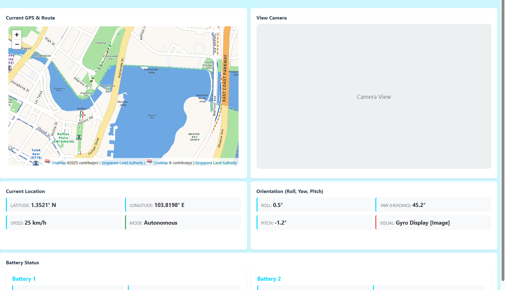
Home arranges the map, camera placeholder, location, and orientation panels in a responsive grid.
05 — GPS & Routing
The map fills the page; a floating panel on the right shows live GPS coordinates and holds the controls.
Three ways to place a waypoint, all in the Waypoint Manager card:
Every waypoint pin can be dragged directly on the map to fine-tune its position, and clicking a waypoint in the list (not its ×) re-centers the map on it. Waypoints persist automatically between sessions; nothing to save manually.
By default the map uses OneMap and needs internet access. With Offline Map Fallback enabled in Settings (section 07), the app switches automatically to a locally stored map the moment it detects no internet connection, and switches back once connectivity returns; no action needed on this page either way.
06 — Battery (BMS)
This page talks directly to the battery management system over RS485; there is no separate bridge application to run first.
Note which COM port Windows assigns it.
Use Refresh if the port isn't listed yet. Baud rate defaults to 9600, matching the hardware.
The app polls both battery packs, Modbus slave addresses 0x81 and 0x82, automatically once connected, and remembers this port/baud rate for next time.
| Panel | Shows |
|---|---|
| Hero stats | Total voltage, state of charge, current, live power |
| Cell Voltage Grid (24S) | All 24 cells, colour-flagged against the pack average |
| Health Report | Cycle count, remaining capacity, avg/max/min cell voltage, cell differential |
| Thermal Management | T1 / T2 sensors and MOSFET temperature |
| Live System Log | Connection events and read errors, newest first |
Use the Battery 1 / Battery 2 tabs to switch which pack the panels are showing; both are polled in the background regardless of which tab is active.
A red alarm indicator appears if any temperature sensor exceeds 60°C or total voltage drops below 42V.
If a reading looks wrong, it helps to verify it independently with BMS Tool, the battery manufacturer's own Windows diagnostic utility, connected to the same RS485 line. It shows the same registers the app reads, per battery, addressed individually:
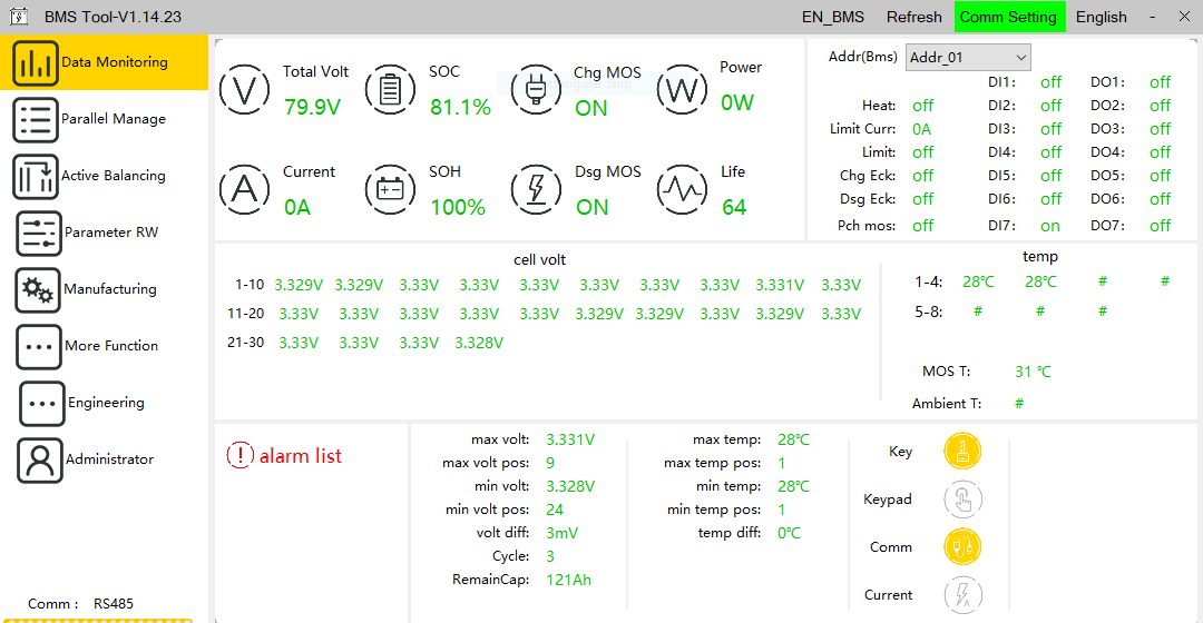
BMS Tool, Battery 1 (Addr_01): total voltage, SOC, per-cell voltage grid, and temperatures.
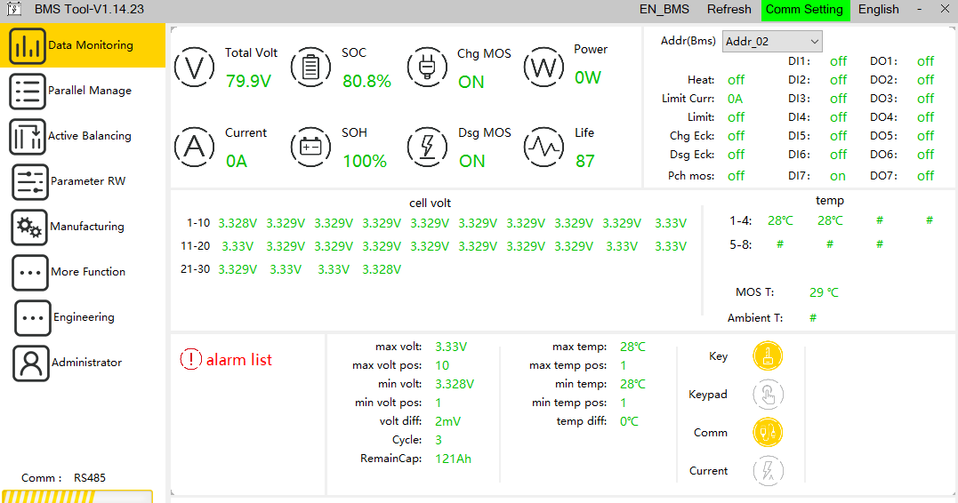
BMS Tool, Battery 2 (Addr_02): same layout, second pack.
BMS Tool's own Addr_01 / Addr_02 dropdown is a separate addressing scheme from the app's Modbus slave addresses (0x81 / 0x82); see the case study in section 10 for why both packs need distinct addresses at all.
07 — Settings
Four groups, top to bottom:
COM Port, Baud Rate, and Update Rate — reference fields for the connected serial hardware.
Camera 1 IP — reserved for the IP camera feed (not yet active, see section 10).
Test Alarm plays the alert sound to confirm audio output is working.
08 — Offline Map Data
The offline map needs a local tile package that isn't included by default. The quickest way to get one:
Download MOBAC (Mobile Atlas Creator, free). Choose the OpenStreetMap Mapnik map source, select the area you need, and export as MBTiles (SQLite).
Save it as exactly:
App/Map/offline-data/singapore.mbtiles
Restart the app, open Settings, and turn on Offline Map Fallback. The status line will read "Offline map data found" once it's picked up correctly.
Covering a wider area at higher zoom levels produces a much larger file. For anything beyond a small demo area, see App/Map/offline-data/README.md for building a package with Planetiler instead.
09 — Closing the App
The window has no title bar and won't close on its own; this is deliberate, so the app can't be dismissed accidentally while the boat is operating. Use the in-app exit control and enter the admin password configured in App/.env (section 02, step 3). An incorrect password shows an Access Denied dialog and the window stays open.
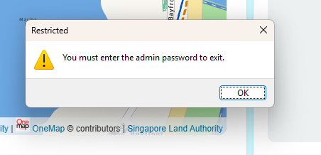
What you'll see if you try to close the window without the admin password.
10 — Troubleshooting
App/.env either doesn't exist or ADMIN_PASSWORD is unset. Check the terminal the app was launched from for a startup warning, then redo section 02 step 3.
The .mbtiles file described in section 08 isn't in place, or the app hasn't been restarted since adding it.
Expected for now; the camera proxy service is a placeholder and no live feed is wired up yet. This is tracked as in-progress, not a fault in your setup.
The weather dashboard reads from a local Flask service that isn't started by default outside of start-app.bat. See README.md in the repo root for running weatherdata.py and server.py directly.
Resolved during commissioning
With both battery packs physically connected, the BMS software could only detect one pack at a time, never both simultaneously, making it impossible to read live values from the second pack.
Root cause
A serial communication address conflict: both battery packs shipped configured to the same communication address (Addr_01), so they collided on the shared RS485 bus instead of responding individually.
Resolution
One pack's communication address had to be changed manually: splicing into its communication line, connecting it to the manufacturer's programming tool, and reassigning the address in the manufacturer software. Final addressing: Battery 1 = 0x01, Battery 2 = 0x02.
If you ever swap in a replacement battery pack, check its address before wiring it in; a fresh pack from the manufacturer is likely to default back to Addr_01 and collide with whichever pack already holds that address.
11 — Quick Reference
| App login | admin / admin |
| Exit / admin unlock password | set in App/.env |
| BMS baud rate (default) | 9600 |
| BMS slave addresses | 0x81 (Battery 1), 0x82 (Battery 2) |
| Weather API port | 127.0.0.1:5000 |
| Admin password | App/.env |
| Saved waypoints | App/user-data/waypoints.json |
| App preferences (map mode, offline fallback) | App/user-data/app-settings.json |
| Offline map tiles | App/Map/offline-data/singapore.mbtiles |
| BMS connection logic | App/services/bmsService.js |
12 — Field Deployment & Network Test
Before relying on a live camera feed on the water, the wireless link that will carry it was tested on site at Eco Lake, Singapore Botanic Gardens (Bukit Timah Core), across nine points around the lake.
One router paired with two long-range 5GHz access points covers the lake from opposite shores; the IP camera connects to the router over a direct LAN cable, and every other client, including the test laptop, joins over Wi-Fi.
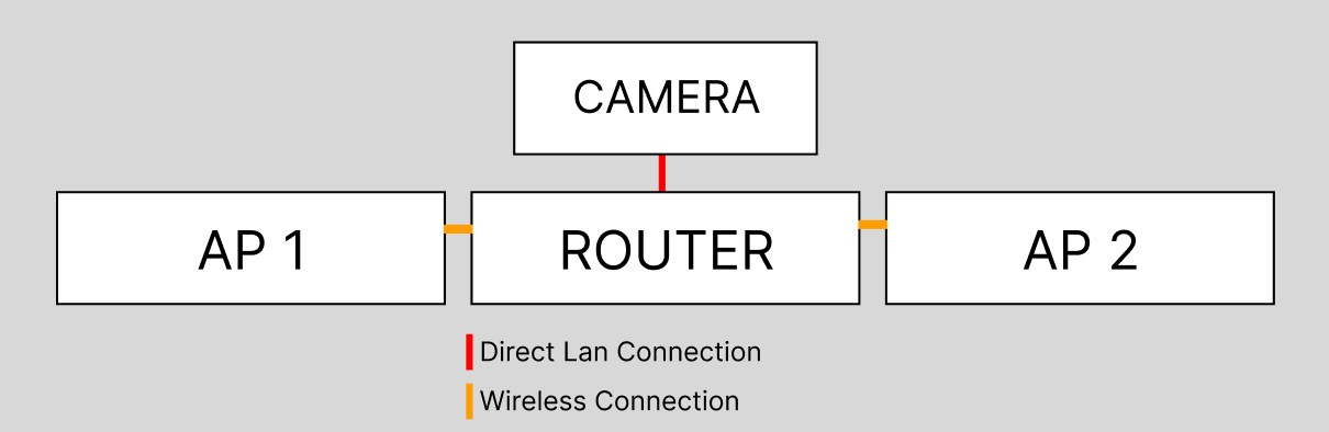
Router + camera in one hut facing the lake; AP1 and AP2 extend coverage to the far shore.
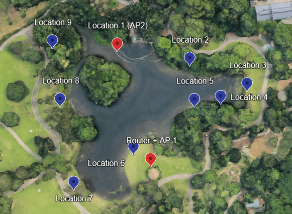
The nine test locations ringing the lake, plus the Router+AP1 and AP2 mounting points.
| Network SSID | WiFi-AX_E5AC_Main |
| Target device | IP camera 192.168.2.122 |
| Hardware | 1 main router + 2× long-range 5GHz access points |
At each of the nine locations, the same sequence was repeated:
Connect the test laptop to WiFi-AX_E5AC_Main and confirm it receives an IP address in the 192.168.2.x subnet.
Open Command Prompt and run ping 192.168.2.122 to confirm the camera is reachable.
Open a browser to the camera's stream endpoint and record round-trip responsiveness.
Log throughput, packet loss, and jitter, then move to the next of the nine locations and repeat.
| Location | Download (Mbps) | Upload (Mbps) | Ping (ms) | Jitter (ms) |
|---|---|---|---|---|
| 1 | 17.6 | 37.4 | 6 | 12 |
| 2 | — | — | — | — |
| 3 | 1.2 | 0.189 | 16 | 7 |
| 4 | 3.5 | 2.9 | 8 | 2 |
| 5 | 22.0 | 10.2 | 7 | 2 |
| 6 | 55.7 | 63.6 | 7 | 9 |
| 7 | 45.5 | 25.3 | 6 | 6 |
| 8 | 46.1 | 23.3 | 6 | 3 |
| 9 | 26.3 | 13.0 | 6 | 8 |
Location 2 recorded no result. Location 3, directly opposite both access points across the widest stretch of water, shows the weakest throughput; worth keeping in mind when planning camera-dependent routes.